Toggle Switch to Pulse Conversion Circuit
2018-02-27
Present Day Note: I wrote this on my old blog on February 27, 2018. The opinions, data, and methodologies reflected here are not necessarily relevant today. This one I rewrote a little bit as I was porting it.
I'm attempting to put a fully operational NAS build into an old stereo enclosure, repurposing the power button to turn the computer on and off. The problem is that computer power buttons are momentary switches that just connect two pins for a brief moment, while this stereo's power button is a toggle switch that stays connected until you flip it again. This means I need a way to convert a toggle switch signal into a momentary pulse.
I could easily do this with a microcontroller, but I decided to try and avoid cutting a sandwich with a chainsaw. It seems wasteful to me to use a whole microcontroller to do one simple task and sleep the rest of the time. So I designed a specialized circuit to do it. I'm by no means an electrical engineer, so this may be a poor design. But stay with me to the end, because this simple thing works (and it's a very short post because it's so simple).
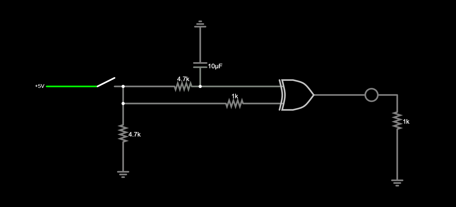
There were several ideas around how I should change a non-momentary toggle switch into a pulse like a momentary button. The simplest of answers I found on the internet was to use a small capacitor to make the motherboard sense the power switch pin being pulled to ground. But I didn't like that because it seemed sketchy. There were some other solutions I came across but I think my roommate pushed me in the right direction when he gave a suggestion about a capacitor and a XOR gate.
When that's closed, the XOR gate will receive a high signal on one of its pins. At that same point, that same signal is being delayed on the other line because of the capacitor (the time it takes to charge and thus the length of the impulse is dependent on the RC pair and I'm not good enough at the calculations to figure out an equation for that). While the capacitor is charging, it will go 'logically high' on the other XOR gate input shortly after. During this time, the XOR will output a high value. When the capacitor is charged, it'll output a low value. This causes the XOR output to pulse.
In the case of turning a computer on, I decided to use a transistor as a gate. When the input of the base is high, the power button header on the motherboard will be closed. With that pulse, it's like pressing the power button. This strategy works incredibly well and it's fairly foolproof. Sometimes I fear the capacitor isn't discharging completely, but I have yet to damage the motherboard after many power cycles so I guess everything is fine so far.
I'm using a 2N2222 transistor and a SN74AHC86 Quad-channel XOR gate (because I couldn't find a single channel XOR gate). I connected VCC and Ground on the USB header on the motherboard. It runs on 5V.
That's really all there is to it. I just wanted to make a dedicated post about this because I didn't see a non-clocked edge detection circuit like this. Hope it's interesting if not helpful to someone out there.