Reverse Engineering a LED Display PCB
2016-01-17
Present Day Note: I wrote this on my old blog on January 17, 2016. The opinions, data, and methodologies reflected here are not necessarily relevant today.
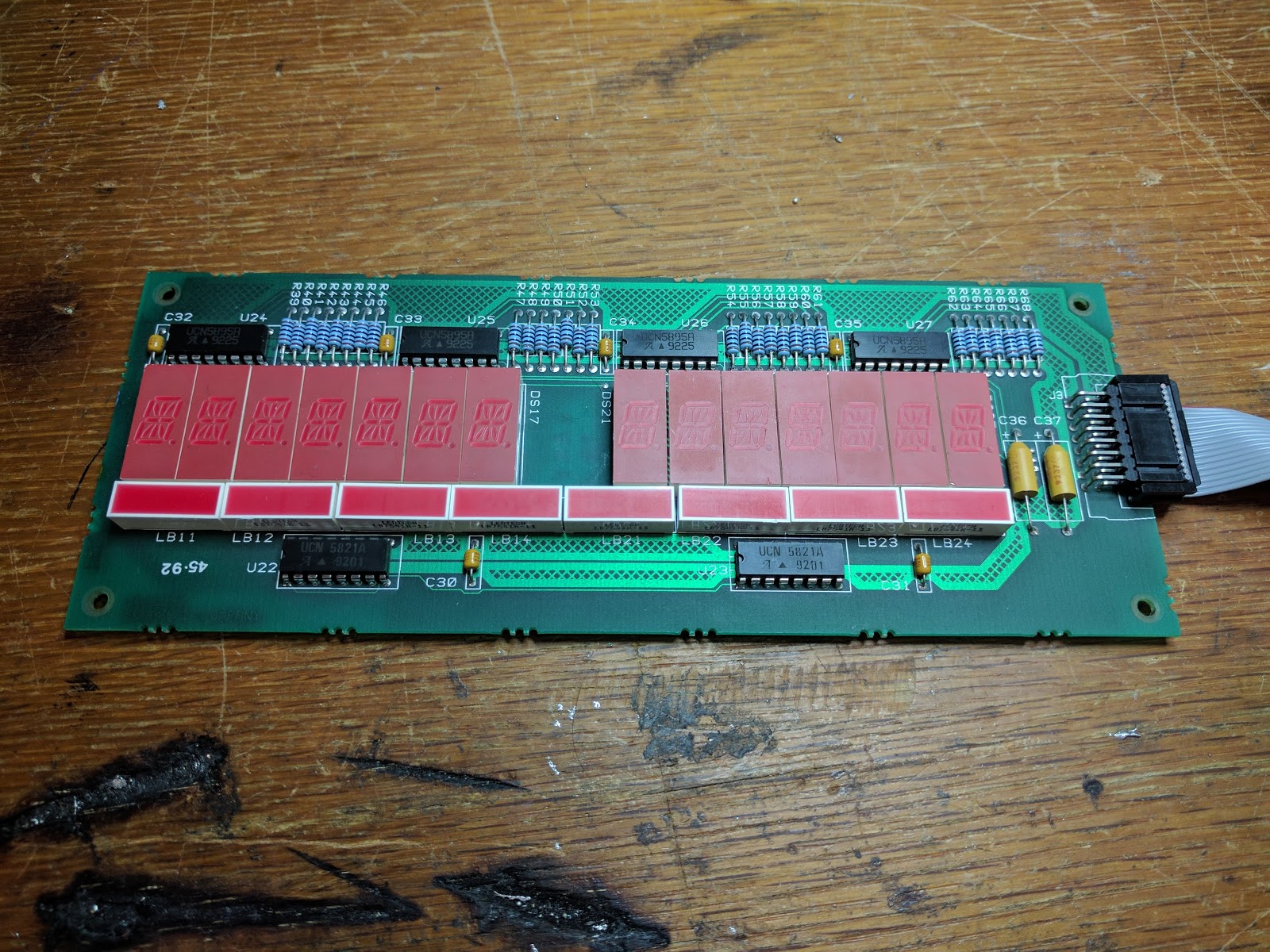
While salvaging the case for my retro gaming computer, I neglected to take the display board apart. That's because I wanted to trace the pinout of the whole thing so I could perhaps drive it and make it into a clock or something. As always, I'm sure this is easier said than done, but you never know unless you try, right? This isn't a super duper complicated circuit, but with several shift registers, 8 light bars, and 14 14-segment displays, programming something to run it may be the real challenge here.
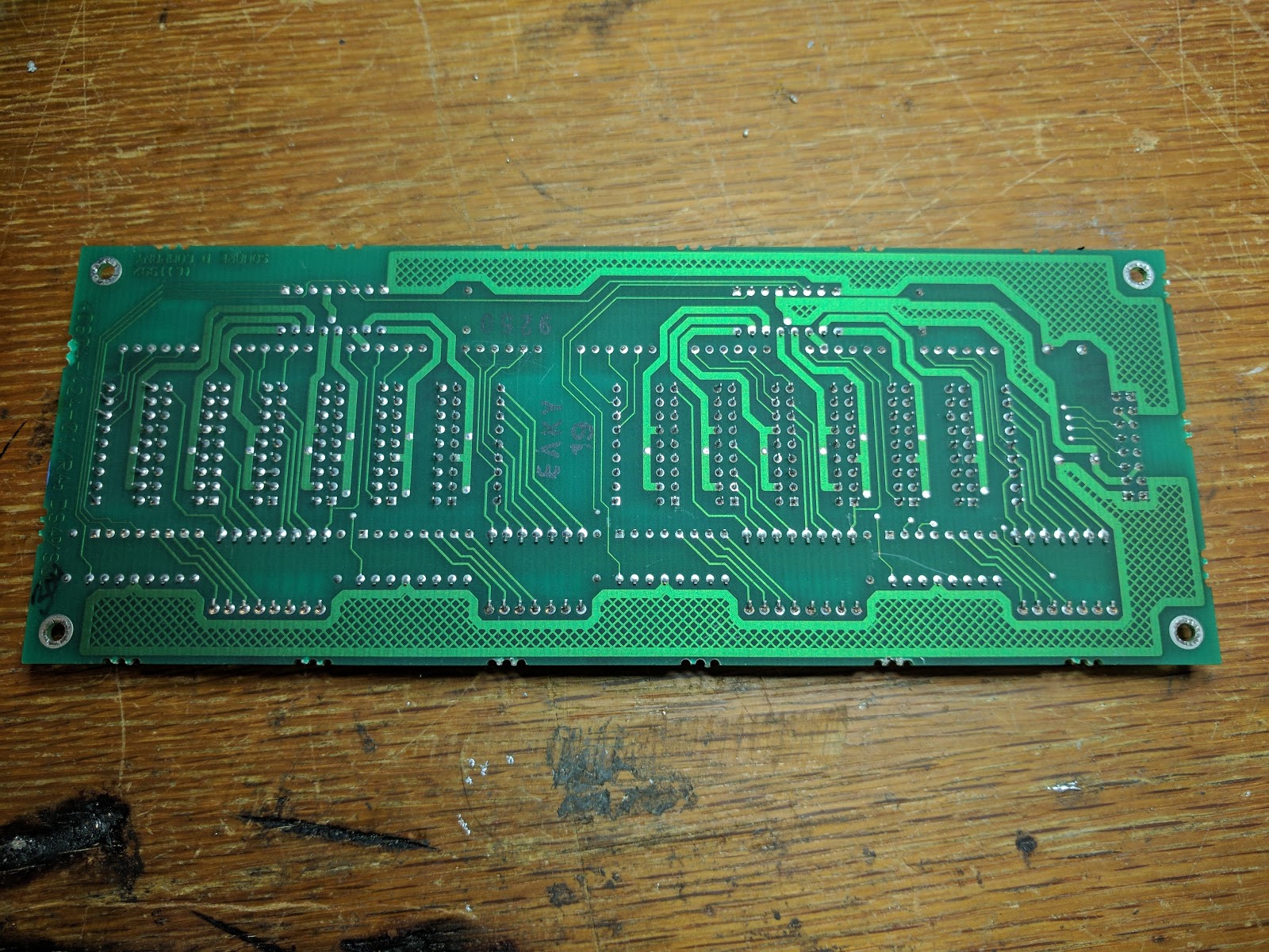
Here is the front and back of the board in question. It has 16 pins that connected it to the main board. With these 16 pins it had to power and control this whole board. It did this, of course, with shift registers. There are two kinds of chips on this board: there are 4 UCN5895As and 2 UCN5821As. The pinouts of these would be my ticket to reverse engineering the whole thing.
First off, I had to find what pins were voltage and ground. I did this by matching the Vcc and ground pins on a chip with corresponding pins on the header with a continuity tester. I then traced the connections on the board to the pins of the shift registers to get this pinout:
| LED Supply | GND | Clock | Serial In | Strobe | OE | Vcc | LED GND |
|---|---|---|---|---|---|---|---|
| LED Supply | LED Supply | GND | NC | NC | Vcc | LED GND | LED GND |
The following section has been slightly rewritten from the original blogpost.
Connecting this all through a series of shift registers will allow me to control the display with just a few pins from the main board. But since this is a chain of shift registers, I need to figure out what bit in the shift register corresponds to each segment of the display.
Through some trial and error, I've discovered that the 48 bits of data correspond to two 16x8 matricies of multiplexed LEDs. At the time, this concept was new to me, and I was fascinated by the idea of controlling so many LEDs with just a few pins. 48 bits to drive 200 LEDs is pretty cool.
The first matrix is the left half of the board, the second is the right half of the board.

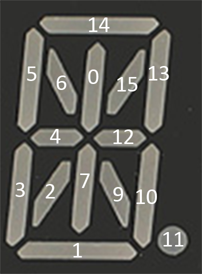
Here are the row numbers for addressing each light in a digit or a bar light.
And the bar LEDs:
| Left | Right | ||||||
|---|---|---|---|---|---|---|---|
| 1, 2, 3 | 11, 10, 7 | 0, 14, 9 | 15, 13, 12 | 1, 2, 3 | 11, 10, 7 | 0, 14, 9 | 15, 13, 12 |
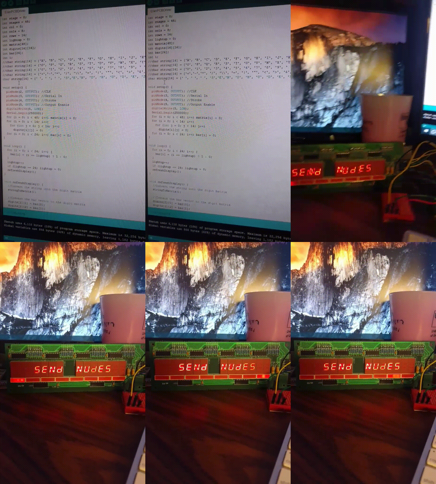
The boiler plate code I've written will write a 14 character string to the board and send pulses down the row of light bar LEDs. Of course, you can make this do anything following the example I've written here. I'm going to make a simple clock out of this. As you can see, the possibilities are endless: